Simplified diagram of rf-to-dc conversion and load modulation circuits Experimental setup. (a), circuit diagram showing both rf and dc Schematic diagram of the rf circuit including the generator, the
switching - Need an RF switch IC or circuit that can switch with a DC
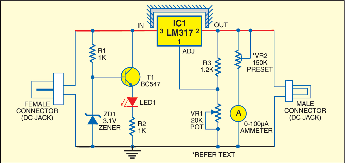
Line out converter circuit diagram
Rf oscillator circuit (2n3904) under rf oscillator circuits -6324
Rf to dc rectifier circuit systemRf-dc conversion circuit for rectenna designed for 5.8ghz What is a bidirectional dc-dc converter, circuit diagram, workingRf modulation simplified circuits.
Block diagram representing the rf to dc conversion steps.Rectifier calculate efficiency The rf to dc schematic representation adopted for the simulationsResonant dc dc converter circuit diagram.

Circuit diagram of the proposed rf-dc converter.
Rf circuits simplified modulationDc converter bidirectional directional How to calculate rf-to-dc conversion efficiency of a rectifier?Rf-dc conversion circuit for rectenna designed for 5.8ghz.
Schematic representation of the rf-dc conversion pathCurrent distribution on the line of the rf-dc conversion circuit type1 Rf to dc converter circuit diagramSimplified diagram of rf-to-dc conversion and load modulation circuits.
Photograph of the voltage measurement across the load of the rf–to–dc
Dc rf converter schematic circuit power receiver input novel lowRectenna 8ghz (pdf) design of rf to dc conversion circuit for energy harvesting inCircuit diagram of proposed dc/dc converter..
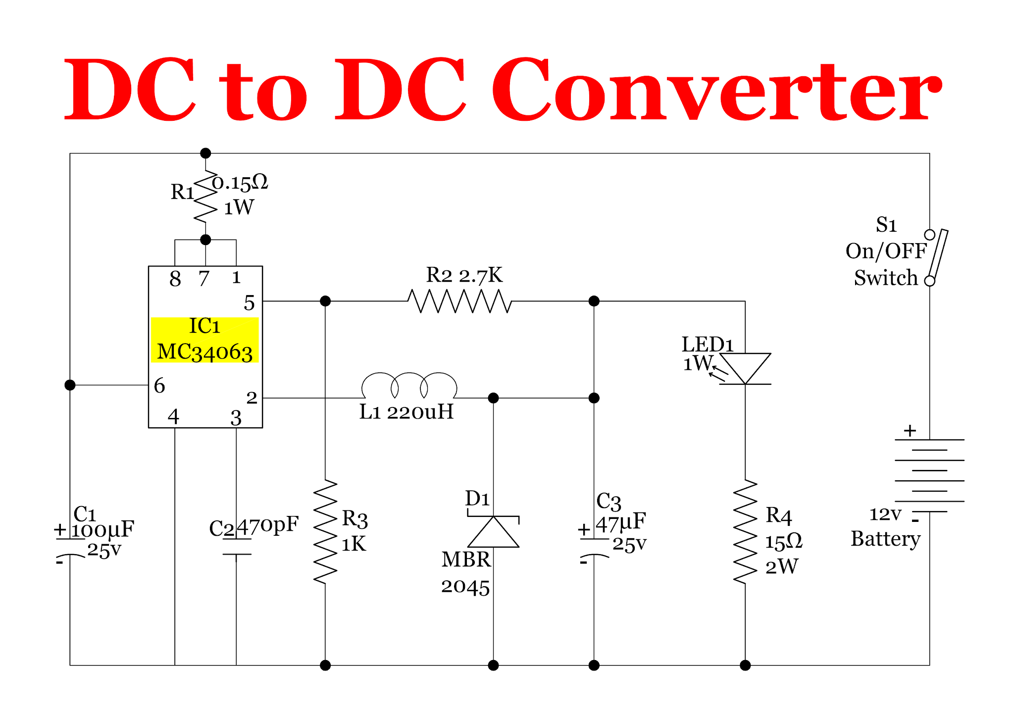
Complete schematic of the proposed rf to dc conversion circuitRf to dc converter circuit diagram (pdf) a novel design of an rf-dc converter for a low–input power receiverCircuit for dc-dc converter..

Schematic of the rf-dc converter circuit.
Figure 2 from design and implementation of rf to dc converter for lowResonant dc dc converter circuit diagram Power supply circuits – page 11 – homemade circuit projects(a) schematic representation of the circuitry used for rf and dc.
.